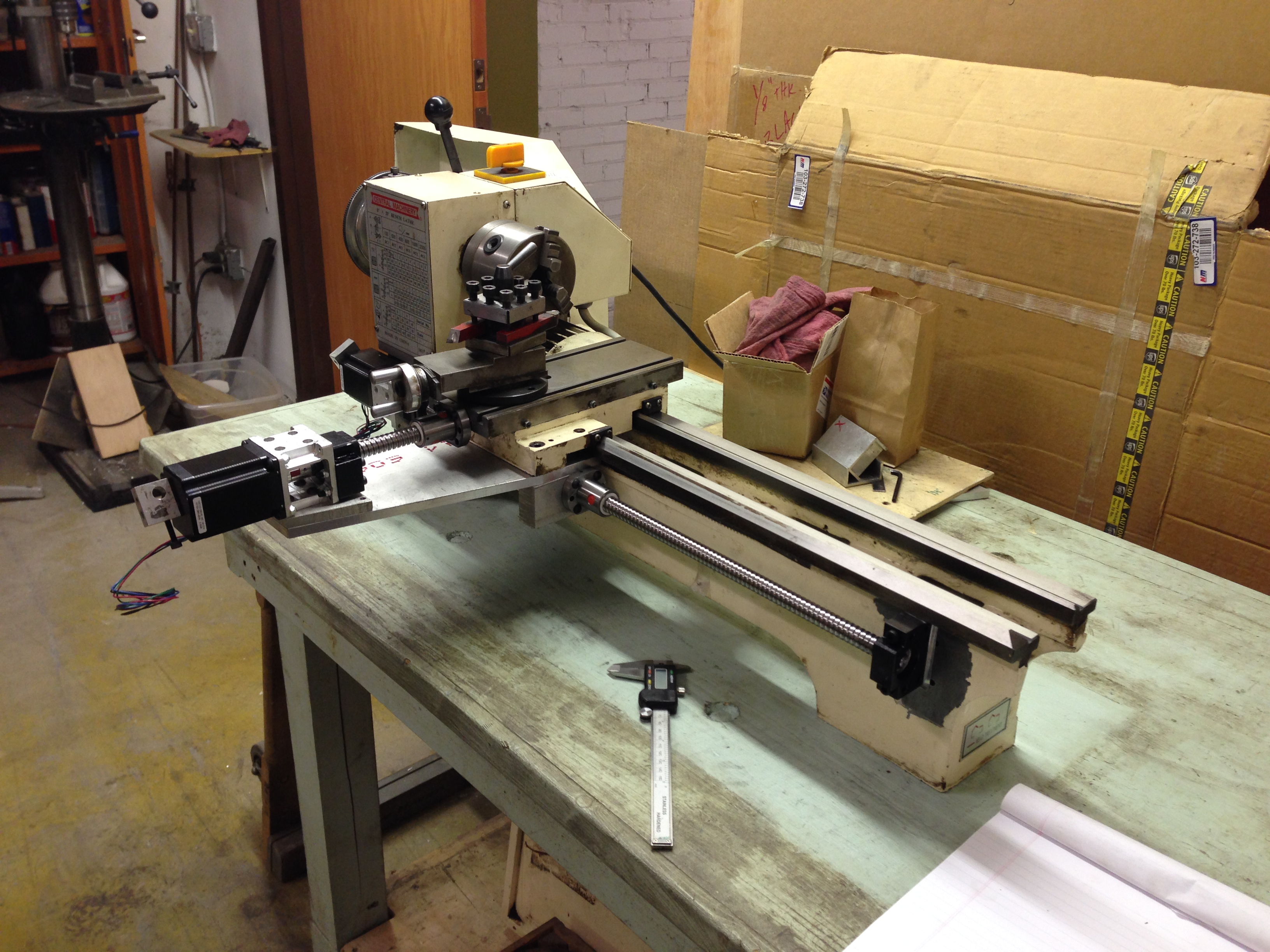
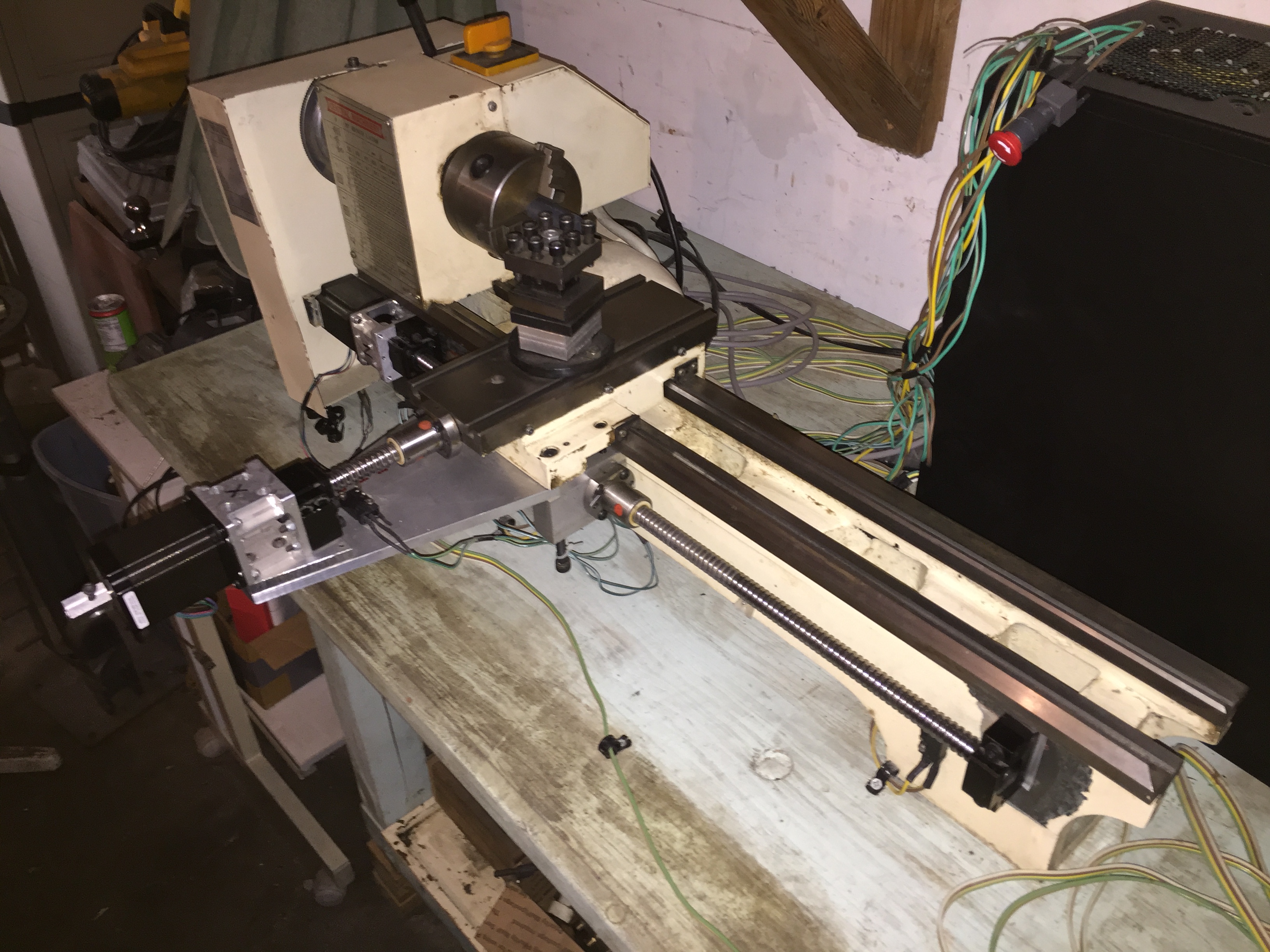
Over the summers of 2014 and 2015, I modified a 9X12 lathe for CNC operation. The project was undertaken by my uncle, a mechanical engineer, and me. The aim of the project was to learn about machinery, electronics and CNC, while creating a tool useful for a wide array of projects.
Lathe Hardware Conversion
The Additional Electronics for Numerical Control
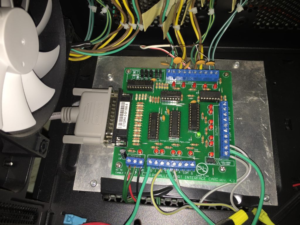
PC Interface Card 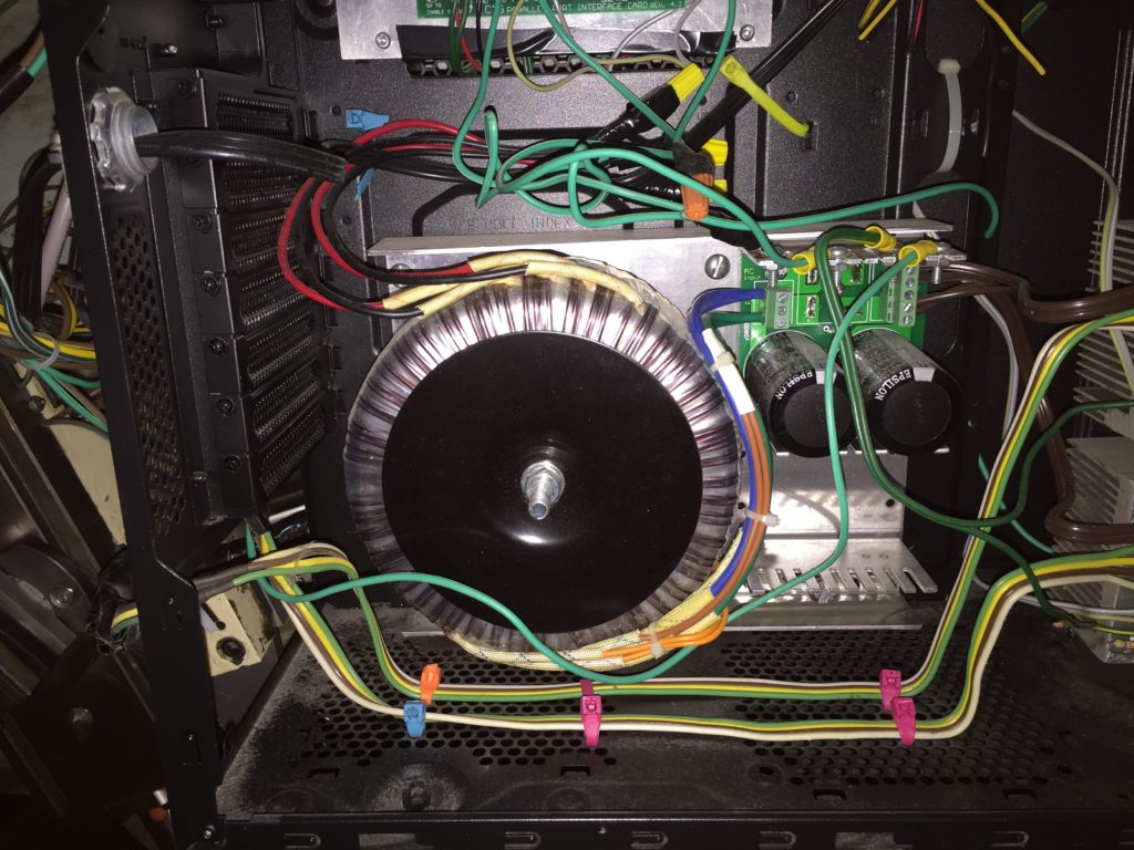
Power Supply 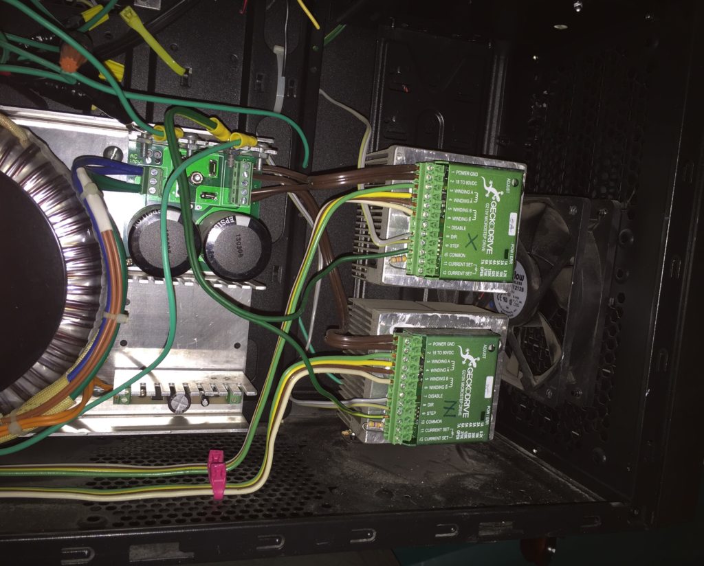
Motor Drives 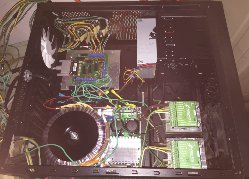
Overall View of Electronics Enclosure
The project started by researching the necessary software toolchain to operate a DIY CNC lathe without buying expensive packages and the required hardware for it also. The solution that I came to was Mach3 running on an XP machine that had a parallel port making sure to use a GPU that is supported by Mach3.
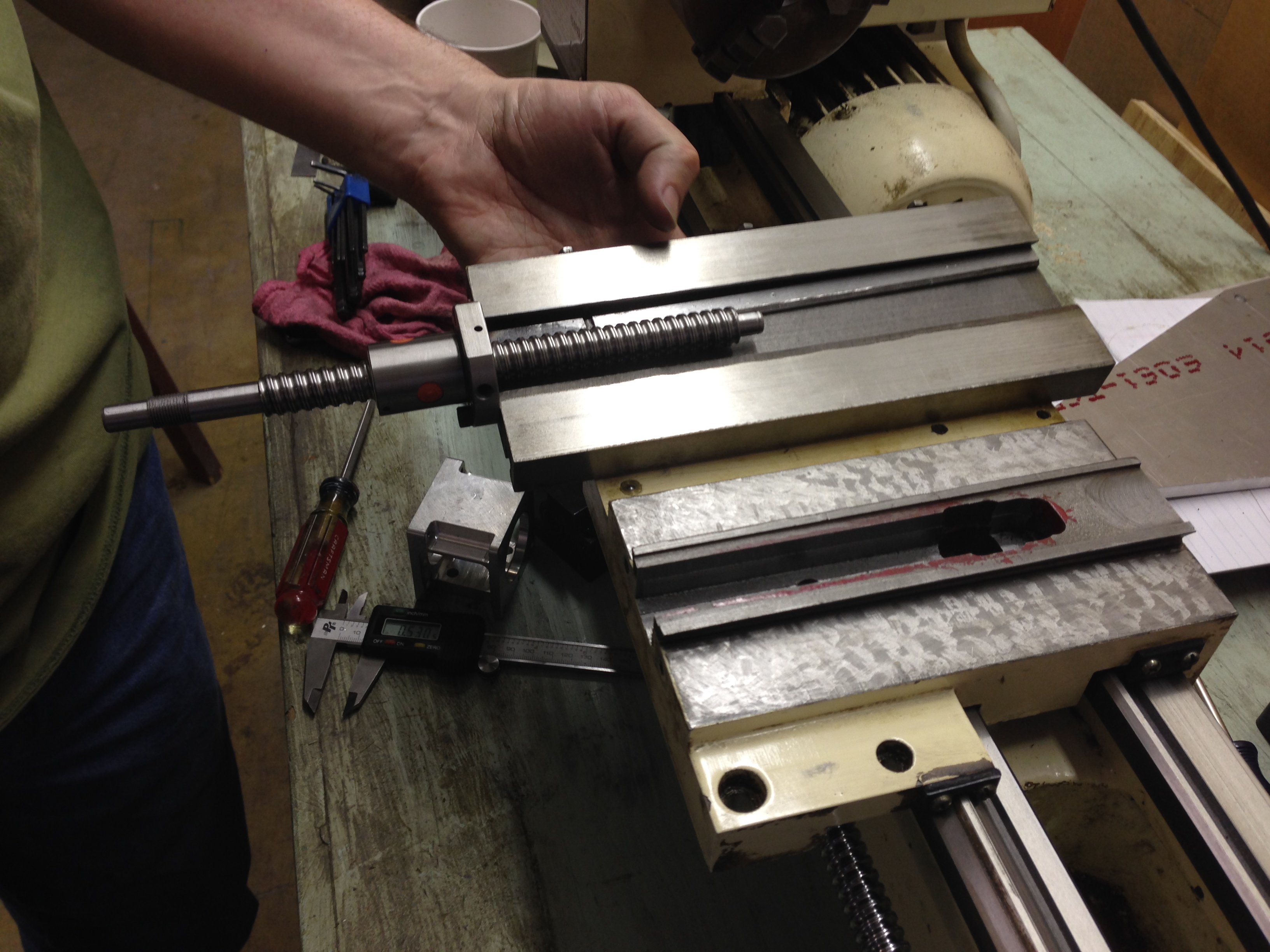
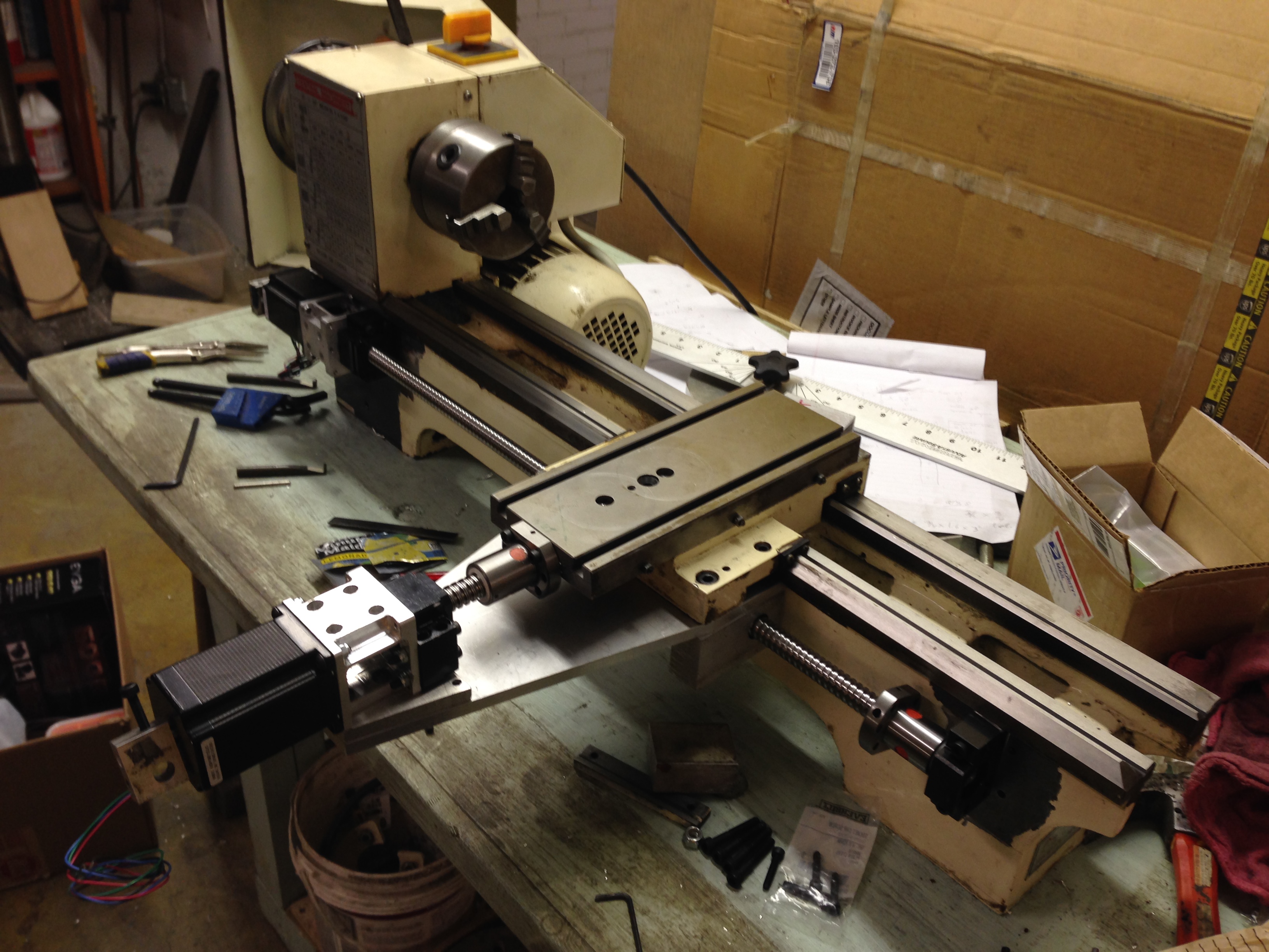
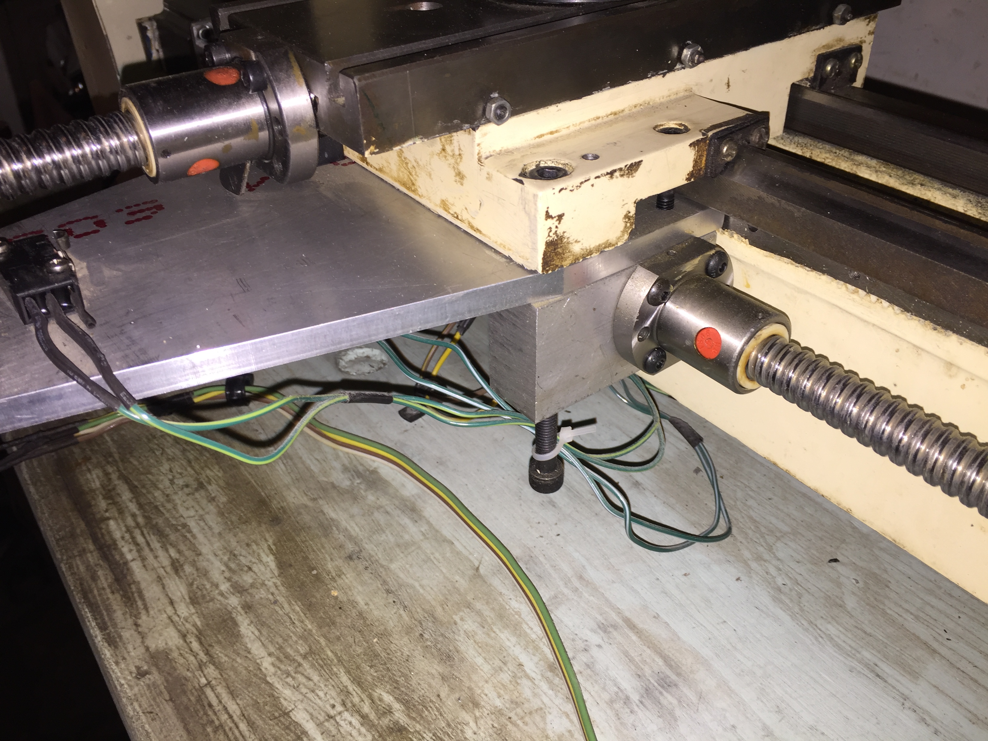
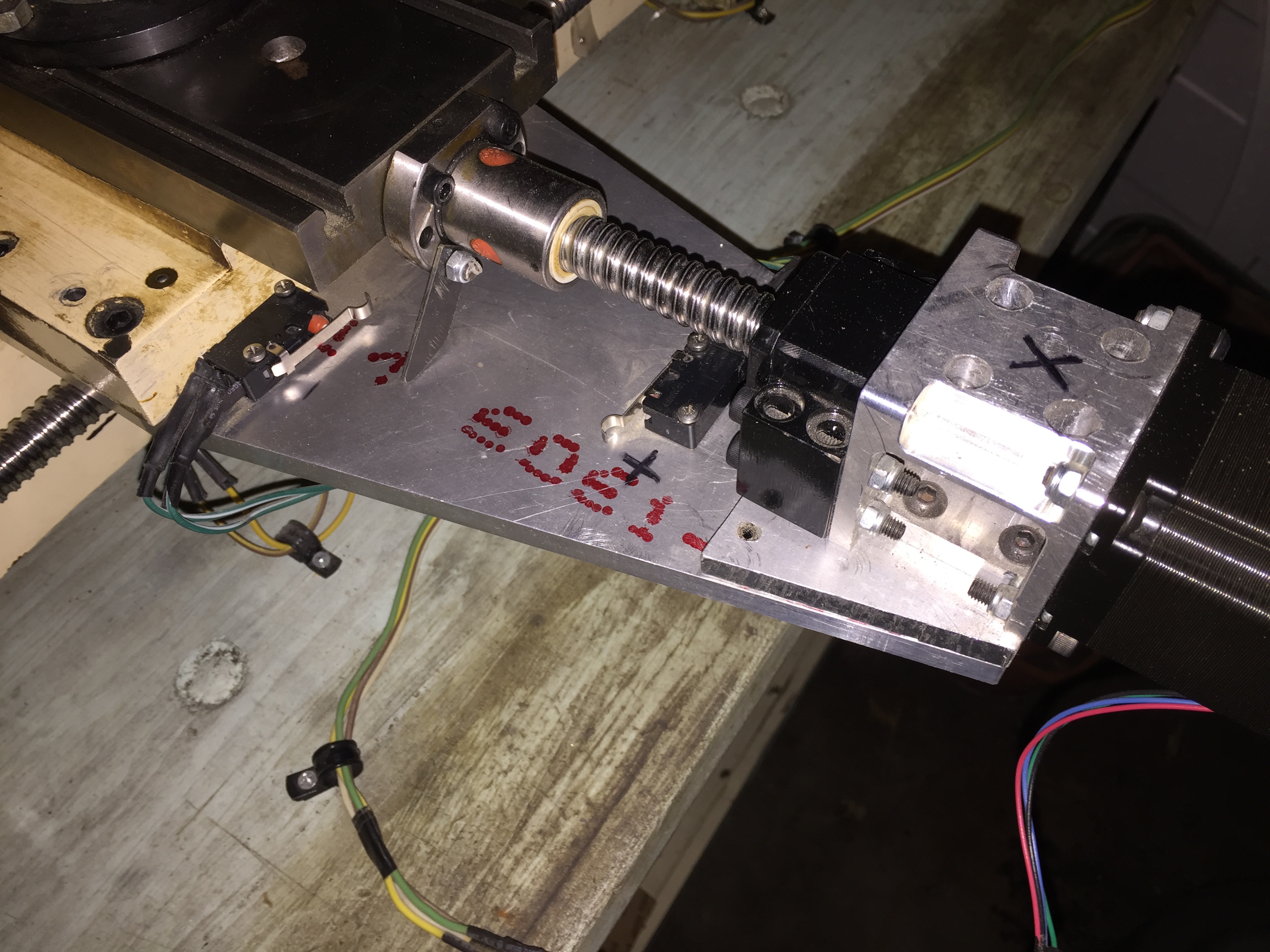
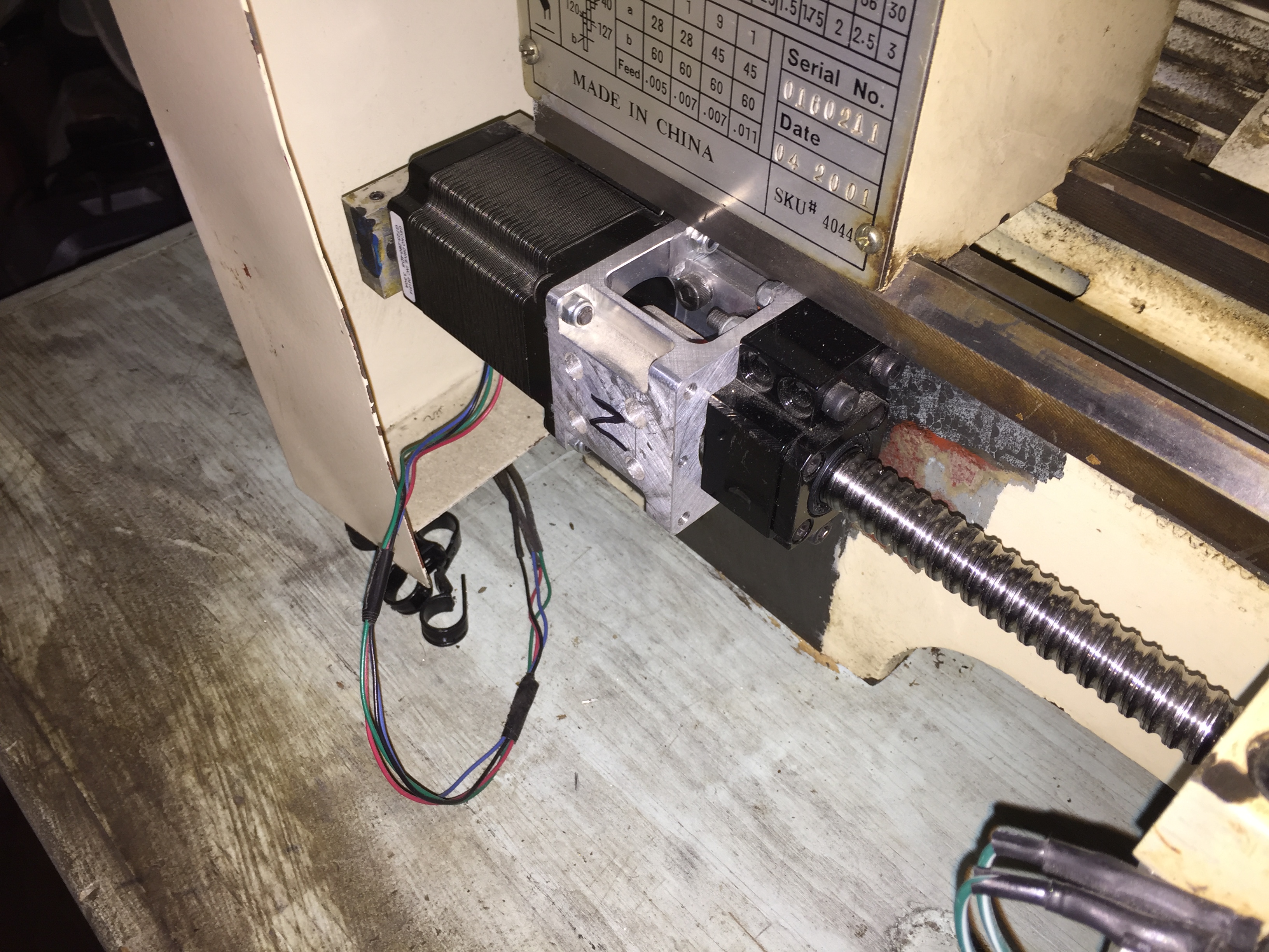
The mechanical hardware needed for a CNC lathe is relatively trivial compared to other CNC machines due to having only two axis (at least on our lathe) of movement instead of 3 or more. Deciding on the motor was tricky however as we needed to make sure that it would have enough torque while also being able to step a fine enough resolution for our purposes. For the linear motion, ballscrews were chosen as they have less backlash than leadscrews, which is especially important in CNC operation unless care is taken to write the tool path with this consideration taken into account. Properly sized motor mounts and thrust bearings were also installed.
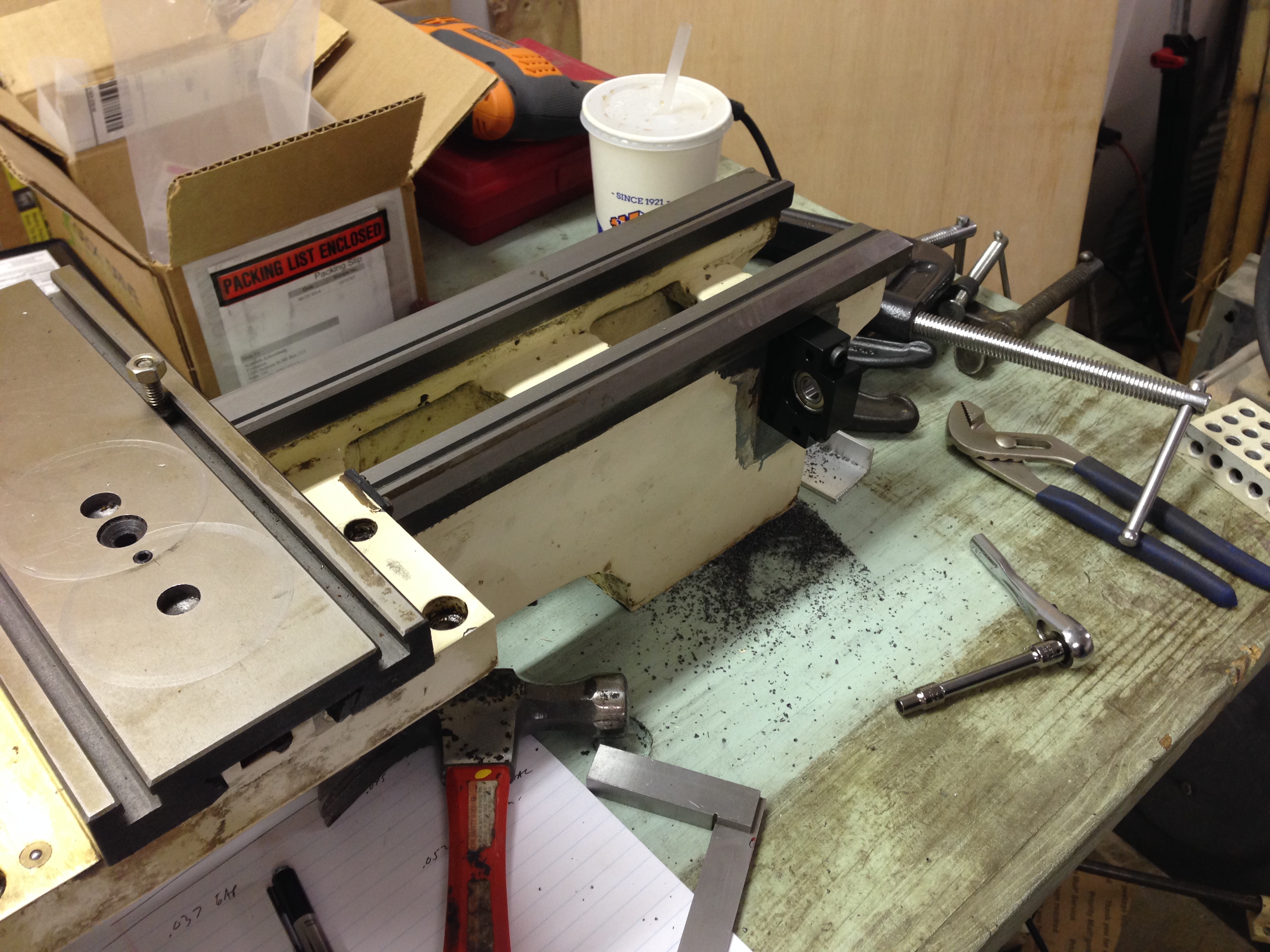
Once the software and hardware for CNC operation was understood, the lathe hardware itself needed to be converted so that motors could be mounted on each axis. Components like the power feed were taken off and metal plates were milled and secured to the lathe to hold the ballscrews, motors, and mounts for each axis.
Everything was then wired. Troubleshooting was easier than expected overall. A capacitor was needed in order to prevent the E-Stop from being triggered from background noise in the wiring due to the EMF generated when the motors were in operation.
